Solve ISO or insulation fault of Solar PV System
Related Products
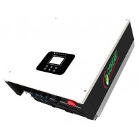
Best inverter for On Grid Solar system 20KW 3phase
This string inverter 20kw 3phase 380V-440Vac is On Grid also known as Grid tied or Grid connected solar inverter, Best inverter for On Grid Solar system. it converts solar DC power(up to 21KW) generated by photovoltaic panels under sunshine to AC power and synchronize the AC power with electrical Grid, so that the power could supply appliances at first and then feed surplus power to utility Grid to get subsidy or reduce electricity bill by FiT(Feed in tariff) policy or net-metering policy issued by your government. With grid string inverter technologies from Emerson, CoHeart China has been developing On Gird solar PV best inverter since 2011 and now we have 3rd generation 2kW-60KW on grid string inverter without fans at highest efficiency! Patented topology and structure design make the grid string inverter robust on Grid adaptability under harsh environment! Best grid tie inverter choice special for bad Grid connection! Register now to get best price of the 20kw on grid string inverter, and 20kw solar power system cost by checking related solar panels and accessories on our store!Best inverter 20kw Features:Transformerless with Three Level topologyMax efficiency 98.5%Dual MPPT with wide input voltage rangeCompact structure No-Fan Design !Best inverter 20kw for on grid Flexibility:Rain proof, dust proof aluminum alloy case (IP65)Easy installation and free maintenanceRS485/WiFi/GPRS (optional) monitoringFree Online upgradingSet all on larger LCD display!Solar Grid string inverter 20kw Reliability:Reliable protection for over/under voltage, anti-islanding,short circuit,overload, ISO detect, RCD detect, over-heating etc.5-years quality warranty at best services! ..

